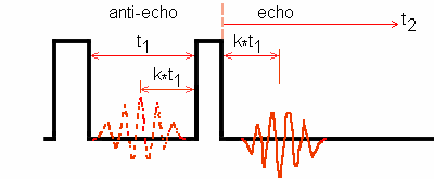
Two-pulse MQ-MAS phase cycling
Below are presented some phase cycling procedures for MQ-MAS with
two-pulse sequence applied to half-integer quadrupole spins:
(1) in amplitude-modulated experiment involving two coherence transfer
pathways,
(2) in phase-modulated experiment involving one coherence transfer pathway.
We only consider the usual case where the receiver can take four phases: 0°, 90°, 180°, and 270°.

Two approaches are used for the simulation of the echo and/or antiecho
amplitudes with SIMPSON1.1.1 Tcl scripts:
(1) filtering the desired coherences (-3Q and/or 3Q after the first pulse),
(2) explicit phase cycling the pulses and the receiver.
For two-pulse 3Q-MAS experiments, these two approaches provide the same simulation data about echo and/or antiecho amplitudes.
Outline (A) Amplitude-modulated experiment for ±3Q-MAS (1) 6-phase cycling for the two-pulse sequence (2) Simulation (3) Result (4) Comment (B) Phase-modulated experiment (a) -3Q-MAS for spin I = 3/2 system (1) 24-phase cycling (2) 12-phase cycling (3) Simulation (4) Result (b) +3Q-MAS for spin I = 5/2 system (1) 24-phase cycling (2) 12-phase cycling (3) Simulation (4) Result (c) -5Q-MAS for spin I = 5/2 system (1) 40-phase cycling (2) 20-phase cycling (3) Simulation (4) Result (C) Conclusion |
(A) Amplitude-modulated experiment for ±3Q-MAS
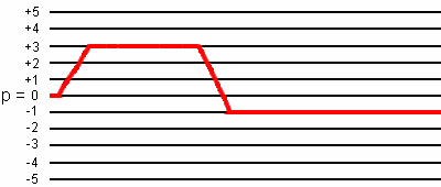
In amplitude-modulated experiment, two coherence transfer pathways 0Q -> -3Q -> -1Q and 0Q -> 3Q ->-1Q are selected. The phase cycling is defined with the two coherence transfer pathways. That is, the phase cycling must be identical for the two coherence transfer pathways.

The total pathway phase φpath for the coherence transfer
pathway 0Q -> -3Q -> -1Q is defined by:
φpath = -3*φ1 + 2*φ2 + φrec,
that for the coherence transfer pathway 0Q -> +3Q -> -1Q is defined by:
φpath = +3*φ1 - 4*φ2 + φrec,
where
φ1 is the first-pulse phase;
φ2 is the second-pulse phase;
φrec is the receiver phase.
The receiver phase is defined with the condition: φpath
= 0. Therefore, we have two equations
for the receiver phase with two parameters:
φrec = +3*φ1 - 2*φ2,
φrec = -3*φ1 + 4*φ2.
(1) 6-phase cycling
The receiver phase is defined with the condition: φ2 = 0;
the two equations for the receiver phase
become:
φrec = +3*φ1,
φrec = -3*φ1.
The corresponding solution is: φ1 takes six values.
| φ1 | 0° 60° 120° 180° 240° 300° |
|---|---|
| φ2 | 0° |
| φrec | 0° 180° |
This is the well-known phase-cycling procedure from [A. Medek, J. S. Harwood, and L. Frydman, J. Am. Chem. Soc. 117, 12779-12787 (1995)] for spin I = 3/2, 5/2, and 7/2 systems.
(2) Simulation
We provide SIMPSON1.1.1 Tcl scripts for simulating the echo and antiecho
amplitude versus a pulse duration with two approaches:
(1) filtering the desired coherences (-3Q and 3Q after the first pulse);
(2) explicit phase cycling the pulses and the receiver.
| Duration | Filtering | 6-phase cycling |
|---|---|---|
| 1st-pulse | al-filtering-p1 | al-6-cycling-p1 |
| 2nd-pulse | al-filtering-p2 | al-6-cycling-p2 |
(3) Result
When the amplitudes are normalized to the number of phase cycling, these two approaches provide the same simulation data about echo and antiecho amplitude for spin I = 3/2, 5/2, and 7/2 systems.
(4) Comment
A 36-phase cycling for two-pulse sequence is available, but the phases of the receiver are different of 0°, 90°, 180° and 270°.
(B) Phase-modulated experiment
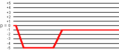
In some 2D experiments such as the double resonance MQ-HETCOR experiment, one coherence transfer pathway is required. For spin I = 3/2 system, the coherence transfer pathway 0Q -> -3Q -> -1Q is needed. For spin I = 5/2 system, the coherence transfer pathway 0Q -> 3Q -> -1Q is needed.
In phase-modulated experiment, phase cycling is defined with the desired coherence transfer pathway.
(a) -3Q-MAS for spin I = 3/2 system
Two phase cycling procedures are possible: one involving 24-phase cycling from [S. H. Wang, S. M. De Paul, and L. M. Bull, J. Magn. Reson. 125, 364-368 (1997)] and one involving 12-phase cycling [S. P. Brown and S. Wimperis, J. Magn. Reson. 128, 42-61 (1997)].

(1) 24-phase cycling
The total pathway phase φpath for the coherence transfer
pathway 0Q -> -3Q -> -1Q is defined by:
φpath = -3*φ1 + 2*φ2 + φrec.
The receiver phase is defined with the conditions: φpath = 0;
therefore φrec = 3*φ1 - 2*φ2.
φ1 takes six values: 0°, 60°, 120°, 180°, 240°, and 300°;
φ2 takes four values: 0°, 90°, 180°, and 270°.
| φ1 | 0° 60° 120° 180° 240° 300° |
|---|---|
| φ2 | {0°}X6 {90°}X6 {180°}X6 {270°}X6 |
| φrec | {0° 180°}X3 {180° 0°}X3 |
Comments
If we reduce the number of phases of the second pulse from four to two as in the following table:
| φ1 | 0° 60° 120° 180° 240° 300° |
|---|---|
| φ2 | {0°}X6 {180°}X6 |
| φrec | 0° 180° |
the two coherence transfer pathways 0Q -> -3Q -> -1Q and 0Q -> 3Q ->-1Q are selected. This is due to the fact that alternating the phase of the second pulse in a two-pulse spin-echo sequence does not change the sign of the echo and that of the antiecho.
(2) 12-phase cycling
The total pathway phase φpath for the coherence transfer pathway
0Q -> -3Q -> -1Q is defined by:
φpath = -3*φ1 + 2*φ2 + φrec.
The receiver phase is defined with the conditions: φpath = 0
and φ2 = 0;
therefore φrec = 3*φ1.
To select only the desired coherence transfer pathway, φ1 takes 12 values.
| φ1 | 0° 30° 60° 90° 120° 150° 180° 210° 240° 270° 300° 330° |
|---|---|
| φ2 | 0° |
| φrec | 0° 90° 180° 270° |
(3) Simulation
We provide SIMPSON1.1.1 Tcl scripts for simulating the echo amplitude versus a
pulse duration with two approaches:
(1) filtering the desired coherences (-3Q after the first pulse);
(2) explicit phase cycling the pulses and the receiver.
| Duration | Filtering | 24-ph cycling | 12-ph cycling |
|---|---|---|---|
| 1st-pulse | na-filt-p1 | na-24-cycl-p1 | na-12-cycl-p1 |
| 2nd-pulse | na-filt-p2 | na-24-cycl-p2 | na-12-cycl-p2 |
(4) Result
When the amplitudes are normalized to the highest number of phase cycling, these two approaches provide the same simulation data about -3Q echo amplitude for spin I = 3/2 system and about -3Q antiecho amplitude for spin I = 5/2 system.
(b) +3Q-MAS for spin I = 5/2 system
Two phase cycling procedures are possible: one involving 24-phase cycling from [C. Fernandez, C. Morais, J. Rocha, and M. Pruski, Solid State NMR 21, 61-70 (2002)] and one involving 12-phase cycling [S. P. Brown and S. Wimperis, J. Magn. Reson. 128, 42-61 (1997)].

(1) 24-phase cycling
The total pathway phase φpath for the coherence transfer
pathway 0Q -> +3Q -> -1Q is defined by:
φpath = 3*φ1 - 4*φ2 + φrec.
The receiver phase is defined with the condition: φpath = 0;
therefore φrec = -3*φ1 + 4*φ2.
φ1 takes six values: 0°, 60°, 120°, 180°, 240°, and 300°;
φ2 takes four values: 0°, 90°, 180°, and 270°.
| φ1 | 0° 60° 120° 180° 240° 300° |
|---|---|
| φ2 | {0°}X6 {90°}X6 {180°}X6 {270°}X6 |
| φrec | 0° 180° |
Comments
If we reduce the number of phases of the second pulse from four to two as in the following table:
| φ1 | 0° 60° 120° 180° 240° 300° |
|---|---|
| φ2 | {0°}X6 {180°}X6 |
| φrec | 0° 180° |
the two coherence transfer pathways 0Q -> -3Q -> -1Q and 0Q -> 3Q ->-1Q are selected. This is due to the fact that alternating the phase of the second pulse in a two-pulse spin-echo sequence does not change the sign of the echo and that of the antiecho.
(2) 12-phase cycling
The total pathway phase φpath for the coherence transfer
pathway 0Q -> +3Q -> -1Q is defined by:
φpath = 3*φ1 - 4*φ2 + φrec.
The receiver phase is defined with the conditions: φpath
= 0 and φ2 = 0;
therefore φrec = -3*φ1.
To select only the desired coherence transfer pathway, φ1 takes 12 values.
| φ1 | 0° 30° 60° 90° 120° 150° 180° 210° 240° 270° 300° 330° |
|---|---|
| φ2 | 0° |
| φrec | 0° 270° 180° 90° |
(3) Simulation
We provide SIMPSON1.1.1 Tcl scripts for simulating the echo amplitude versus a
pulse duration with two approaches:
(1) filtering the desired coherences (3Q after the first pulse);
(2) explicit phase cycling the pulses and the receiver.
| Duration | Filtering | 24-ph cycling | 12-ph cycling |
|---|---|---|---|
| 1st-pulse | al-filt-p1 | al-24-cycl-p1 | al-12-cycl-p1 |
| 2nd-pulse | al-filt-p2 | al-24-cycl-p2 | al-12-cycl-p2 |
(4) Result
When the amplitudes are normalized to the highest number of phase cycling, these two approaches provide the same simulation data about 3Q echo amplitude for spin I = 5/2 system and about 3Q antiecho amplitude for spin I = 3/2 system.
(c) -5Q-MAS for spin I = 5/2 system
A phase cycling procedure involving 40-phase cycling is provided by [L. Delevoye and coworkers, Solid State NMR 22, 501-512 (2002)].

(1) 40-phase cycling
The total pathway phase φpath for the coherence transfer
pathway 0Q -> -5Q -> -1Q is defined by:
φpath = -5*φ1 + 4*φ2 + φrec.
The receiver phase is defined with the condition: φpath = 0;
therefore φrec = 5*φ1 - 4*φ2.
φ1 takes ten values: 0°, 36°, 72°, 108°, 144°, 180°, 216°, 252°, 288°, and 324°;
φ2 takes four values: 0°, 90°, 180°, and 270°.
| φ1 | 0° 36° 72° 108° 144° 180° 216° 252° 288° 324° |
|---|---|
| φ2 | {0°}X10 {90°}X10 {180°}X10 {270°}X10 |
| φrec | 0° 180° |
(2) 20-phase cycling
The total pathway phase φpath for the coherence transfer
pathway 0Q -> -5Q -> -1Q is defined by:
φpath = -5*φ1 + 4*φ2 + φrec.
The receiver phase is defined with the condition: φpath = 0 and φ2 = 0;
therefore φrec = 5*φ1.
φ1 takes 20 values: 0°, 18°, 36°, 54°, 72°, 90°, 108°, 126°, 144°, 162°, 180°,
198°, 216°, 234°, 252°, 270°, 288°, 306°, 324°, and 342°.
| φ1 | 0° 18° 36° 54° 72° 90° 108° 126° 144° 162° 180° 198° 216° 234° 252° 270° 288° 306° 324° 342° |
|---|---|
| φ2 | 0° |
| φrec | 0° 90° 180° 270° |
(3) Simulation
We provide SIMPSON1.1.1 Tcl scripts for simulating the echo amplitude versus a
pulse duration with two approaches:
(1) filtering the desired coherences (-5Q after the first pulse);
(2) explicit phase cycling the pulses and the receiver.
| Duration | Filtering | 40-ph cycling | 20-ph cycling |
|---|---|---|---|
| 1st-pulse | al-filt-5Q-p1 | al-40-cycl-5Q-p1 | al-20-cycl-5Q-p1 |
| 2nd-pulse | al-filt-5Q-p2 | al-40-cycl-5Q-p2 | al-20-cycl-5Q-p2 |
(4) Result
When the amplitudes are normalized to the highest number of phase cycling, these two approaches provide the same simulation data about -5Q echo amplitude for spin I = 5/2 system.
(C) Conclusion
For two-pulse MQ-MAS sequences, filtering the desired coherences or phase cycling the pulses and the receiver provide the same simulation data about echo and/or antiecho amplitudes.
Reducing the number of phases allows unwanted coherence transfer pathways to be detected.
