SPAM echo/antiecho pulse program for 3QMAS provided by Bruker
This NMR pulse program is for Bruker Avance III spectrometers.
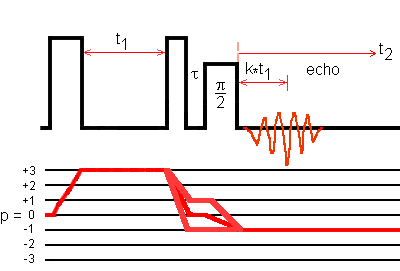
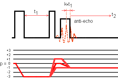
Echo and antiecho parts in a 3QMAS 2D NMR experiment are acquired alternatively. Each part is obtained with a phase-modulated z-filtered MQMAS sequence combined with SPAM to increase the signal amplitude. The three pulse durations are optimized with the conventional z-filter sequence. The echo amplitude and the antiecho amplitude have opposite signs.

Fig. 1: SPAM echo transfer pathways for a spin I = 5/2 system:
0Q -> 3Q -> (1Q, 0Q, and -1Q) -> -1Q.
The phase ph1 of the first pulse is cycled 12 times.
The phase of the second pulse is X;
that of the third pulse is X. The receiver phase is -3*ph1.

Fig. 2: SPAM antiecho transfer pathways for a spin I = 5/2 system:
0Q -> -3Q -> (1Q, 0Q, and -1Q) -> -1Q.
The phase ph1 of the first pulse is cycled 12 times.
The phase of the second pulse is X;
that of the third pulse is -X. The receiver phase is 3*ph1.
After the Fourier transform with respect to t2, a t1-dependent first-order phase correction is performed with the shearing transformation.
; mp3qspam.av

; 3Q MAS pulse program for nuclei with half-integer quadrupole spin,
; experiment with z-filter:
; excitation(+3Q) - conversion(1Q, 0Q, -1Q) - tau - (+X)90°sel - ACQ(-1Q)
; excitation(-3Q) - conversion(1Q, 0Q, -1Q) - tau - (-X)90°sel - ACQ(-1Q)
; uses selective pulse added mixing (SPAM) trick, see Z. Gan;
; 90° selective pulse should be determined first using Hahn-echo,
; determination by single pulse excitation is also possible,
; then optimize P2 and finally P1 using mp3qzqf pulse program;
; 2 or more iterations for P1 and P2 may be necessary;
; for processing shearing transformation is required,
; use AU program xfshear

; parameters:
;ns :  12*n
;d1 :  recycle delay
;p1 :  excitation pulse at pl11
;p2 :  conversion pulse at pl11
;p3 :  90 degree selective pulse at pl21
;pl1 :  = 119 dB (not used)
;pl11 : power level for excitation and conversion pulses
;pl21 : power level for 90° selective pulse, ca. pl11 + 30dB
;d4 :  0.5u
;d0 :  = 1u or longer
;in0 : 1 rotor period for synchronized experiment
;l4: internal counter to select echo or antiecho phase cycling
;l5: number of antiechos to be acquired
;l6: =3 for I=3/2, else =1
;td1 : number of t1-experiments
;FnMODE : Echo-Antiecho
;MC2 : Echo-Antiecho

"l4=1"
define loopcounter echosonly
"echosonly=(td1 - l5*2)/2" ; number of remaining echos to be acquired, they
                      ; are associated with zero-amplitude antiechos,

  ze                  ; clear memory, new data replace old data,
                      ; switch AD converter to replace mode,
                      ; perform DS before next acquisition,
;-----------------------------------------------------------------------
; 0Q -> 3Q -> (1Q, 0Q, and -1Q) -> -1Q signal acquisition alternating
; with 0Q -> -3Q -> (1Q, 0Q, and -1Q) -> -1Q signal acquisition
;-----------------------------------------------------------------------
1 10m
  d1                  ; recycle delay,
  10u pl11:f1         ; 10 microsecond delay,
                      ; set high power in f1 channel,
  (p1 ph1):f1         ; high-power excitation pulse,
  d0                  ; delay between pulses or t1,
  (p2 ph2):f1         ; high-power conversion pulse,
  d4                  ; z-filter delay,
  if "l4 % 2 == 1"    ; % is the remainder operator;
    {                 ; 0Q -> 3Q -> (1Q, 0Q, and -1Q) -> -1Q
                      ; coherence transfer pathway signal acquisition:
    (p3 pl21 ph3):f1    ; selective 90° pulse with phase = 0,
    go=1 ph30           ; signal acquisition with receiver phase = -3*ph1,
    }                   ; loop to 1, ns times for averaging,
  else
    {                 ; 0Q -> -3Q -> (1Q, 0Q, and -1Q) -> -1Q
                      ; coherence transfer pathway signal acquisition:
    (p3 pl21 ph5):f1    ; selective 90° pulse with phase = 180,
    go=1 ph31           ; signal acquisition with receiver phase = 3*ph1,
    }                   ; loop to 1, ns times for averaging,
    3u                  ; do not delete,
  10m wr #0 if #0 zd  ; delay for disk I/O, store signal,
                      ; increase FID number,
                      ; delete memory data,
                      ; do not perform dummy scans
                      ; with next acquisition,
  1m iu4              ; increment loop counter l4 = l4 + 1,
  lo to 1 times 2     ; acquire the other coherence transfer pathway signal,
  1m id0              ; increment delay d0 by in0 (t1 increment),
  1o to 1 times l5    ; next experiment, loop for number of antiechos,
;-------------------------------------------------------------------
;      echo acquisition alternating with zero-amplitude antiecho
;-------------------------------------------------------------------
  if "l6 == 3"        ; spin I = 3/2 case:
    {                   ; increase FID number, that is,
    1m if #0            ; skip 0Q -> 3Q -> (1Q, 0Q, and -1Q) -> -1Q
    }                   ; antiecho transfer pathway signal acquisition,
2 10m
  d1                  ; recycle delay,
  10u pl11:f1         ; 10 microsecond delay,
                      ; set high power in f1 channel,
  (p1 ph1):f1         ; high-power excitation pulse,
  d0                  ; delay between pulses or t1,
  (p2 ph2):f1         ; high-power conversion pulse,
  d4                  ; z-filter delay,
  if "l6 == 3"        ; spin I = 3/2 case:
    {                   ; 0Q -> -3Q -> (1Q, 0Q, and -1Q) -> -1Q
                        ; echo transfer pathway signal acquisition,
    (p3 pl21 ph5):f1    ; selective 90° pulse with phase = 180°,
    go=2 ph31           ; signal acquisition with receiver phase = 3*ph1,
    }                   ; loop to 2, ns times for averaging,
  else                ; spin I > 3/2 case:
    {                   ; 0Q -> 3Q -> (1Q, 0Q, and -1Q) -> -1Q
                        ; echo transfer pathway signal acquisition,
    (p3 pl21 ph3):f1    ; selective 90° pulse with phase = 0°,
    go=2 ph30           ; signal acquisition with receiver phase = -3*ph1,
    }                   ; loop to 2, ns times for averaging,
    3u                  ; do not delete,
  10m wr #0 if #0 zd  ; delay for disk I/O, store signal,
                      ; increase FID number,
                      ; delete memory data,
                      ; do not perform dummy scans
                      ; with next acquisition,
  1m if #0            ; increase FID number, that is, skip antiecho signal,
  1m id0              ; increment delay d0 by in0 (t1 increment),
  1o to 2 times echosonly  ; loop for number of remaining echos,
exit                  ; end of the pulse program

ph1=(12) 0 1 2 3 4 5 6 7 8 9 10 11 ; excitation pulse phase
ph2=     0                         ; conversion pulse phase
ph3=     0                         ; third pulse phase = 0°
ph5=     2                         ; third pulse phase = 180°
ph30=    0 3 2 1                   ; receiver phase for
                                   ; 0Q -> 3Q -> (1Q, 0Q, and -1Q) -> -1Q
                                   ; that is, ph30 = -3*ph1
ph31=    0 1 2 3                   ; receiver phase for
                                   ; 0Q -> -3Q -> (1Q, 0Q, and -1Q) -> -1Q
                                   ; that is, ph31 = 3*ph1
The structure of the SER-data file is simple: the time domaine signals of the coherence transfer pathway 0Q -> 3Q -> (1Q, 0Q, and -1Q) -> -1Q are alternated with those of the coherence transfer pathway 0Q -> -3Q -> (1Q, 0Q, and -1Q) -> -1Q. The first file in this SER-data file is that of the coherence transfer pathway 0Q -> 3Q -> (1Q, 0Q, and -1Q) -> -1Q.